29 August, 2025
Building My Smart Home - Part 2: ESPHome & RF433
Implementing an RF433 gateway using ESPHome and a custom Home Assistant add-on to manage multiple RF433 receivers for my smart home.
- Get started with ESPHome
- First ESPHome Node
- Building the RF433 Gateway
- Plan for RF433 Gateway
- First Prototype
- Integrate with ESPHome
- Custom add-on
- Sending RF433 codes from hassio
- Conclusion
In part 1, I covered the overall design of my smart home, noticeably the choice of RF433 for switches. In this part, I'll dive into the implementation of the RF433 gateway using ESPHome.
Get started with ESPHome
ESPHome is an open-source platform that simplifies the process of creating custom firmware for ESP8266 and ESP32 microcontrollers. It allows you to define your device's configuration using YAML files, making it easy to integrate with hassio.
In fact, I can home-make my own version of ESPHome, by spinning up a web server on the ESP32, and check it periodically from hassio. That's exactly what I did before knowing about ESPHome. However, this approach is more time-consuming and requires maintaining hassio config files. ESPHome abstracts away much of the complexity, allowing me to focus on the functionality rather than the low-level details.
In the diagram below, I compare my custom approach with ESPHome. Note that the human symbol represents parts that need to be maintained separately.
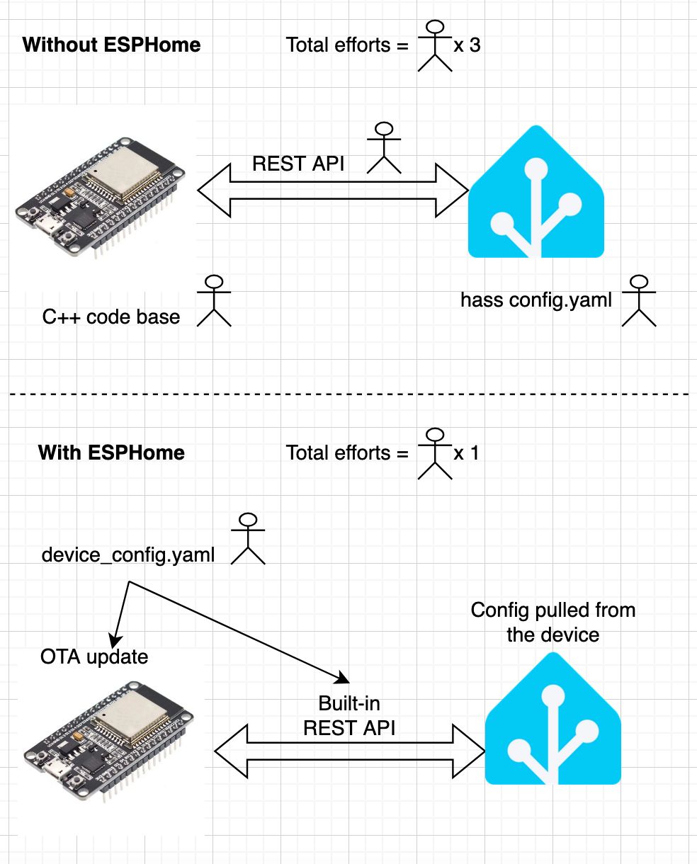
Of course, ESPHome may not provide all the features I need. That's why we will also need to write some custom C++ code to handle specific tasks. I'll go into more detail on that later.
First ESPHome Node
To get started with ESPHome, I first set up a simple ESPHome node for these 2 purposes:
- Detect if the entrance door is locked using an infrared proximity sensor (LM393). I also add red and green LEDs to indicate the lock status.
- Control my interphone, simulate key presses using optocoupler (PC817). This allows me to remotely open the apartment entrance for visitors.
Note: while I wanted to use more modern solutions for the lock, like the SwitchBot Smart Lock, my door is simply not compatible. The door that the old owner installed was a very expensive blind door with skeleton-style key, which is too complicated to be replaced.
The wiring looks like this:
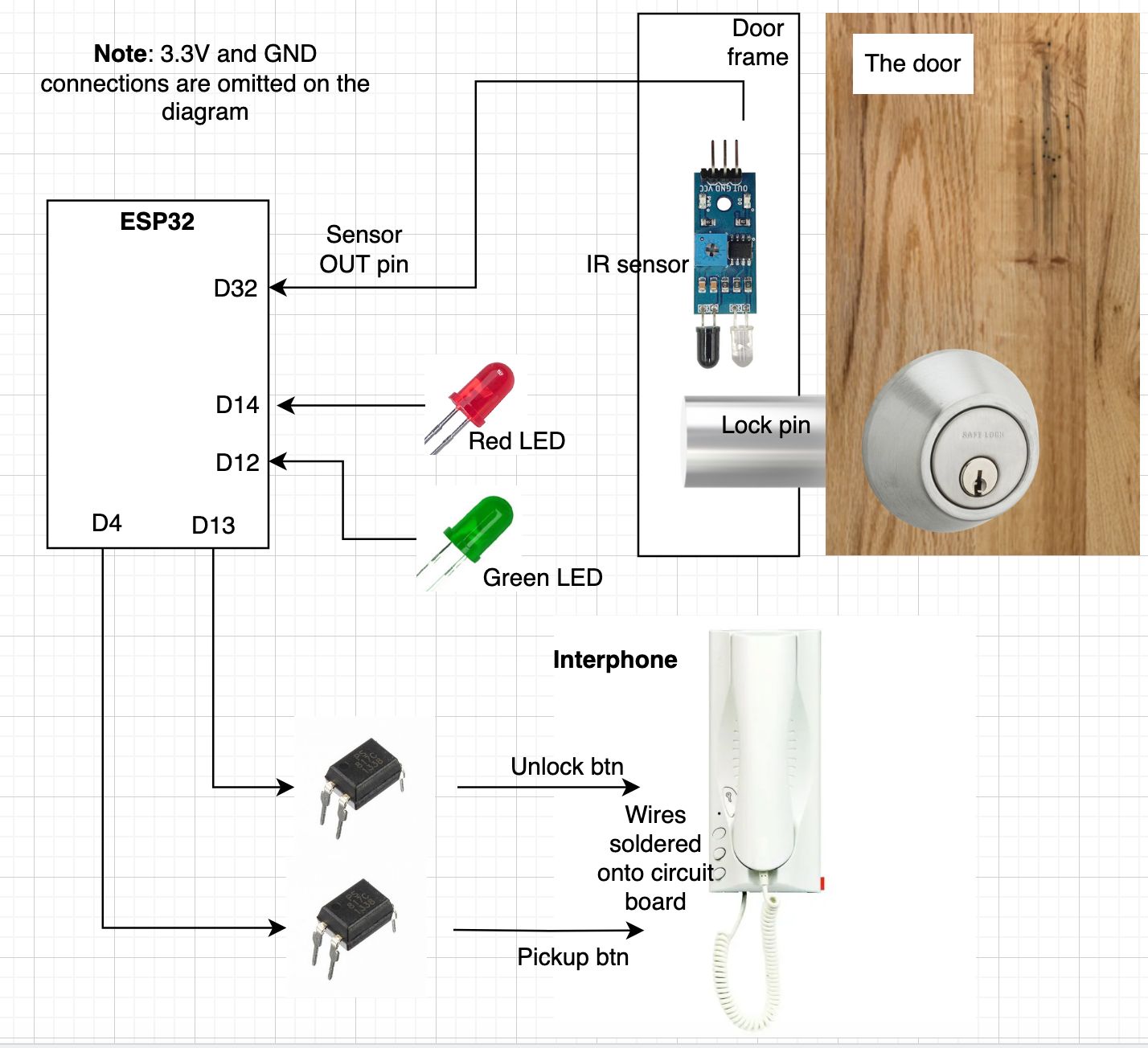
For the interphone, I needed to solder some wires to the PCB of the interphone. The 2 buttons I need to simulate are "unlock" and "pickup". The optocouplers are used to simulate a button press by closing the circuit.
(Sorry for not having any better photos, I forgot to take some before installing it)
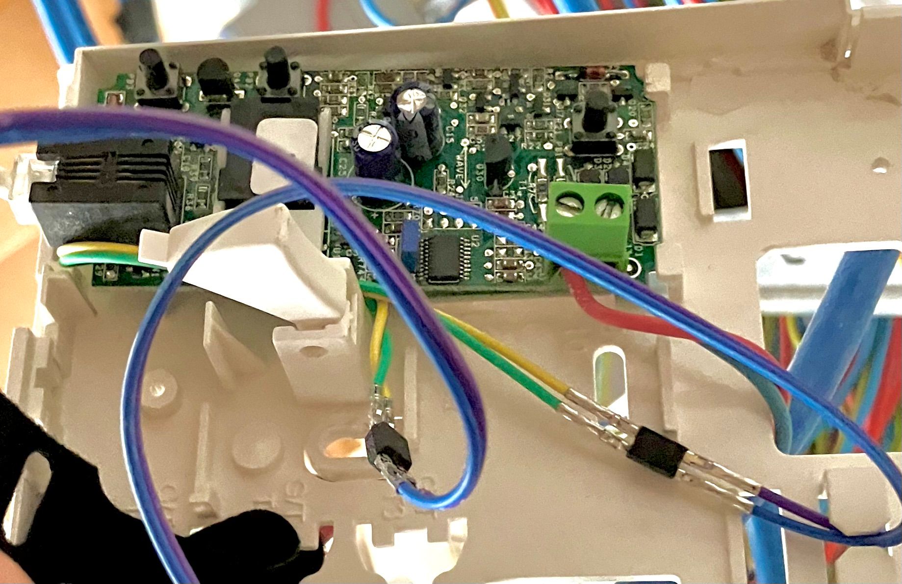
For the logic:
- When the proximity sensor detects the lock pin, it turns on the green LED.
- When the lock pin is not detected, it turns on the red LED.
- When I enable the "Interphone Auto Unlock" switch in hassio, every 10 seconds, it will simulate this sequence: pick up -> wait -> unlock -> wait -> hang up.
The reference YAML config file can be found here.
Flash it to the ESP32:
esphome run my_first_module.yaml
Then add the node to hassio. Now I can see the lock status and control the interphone from hassio:
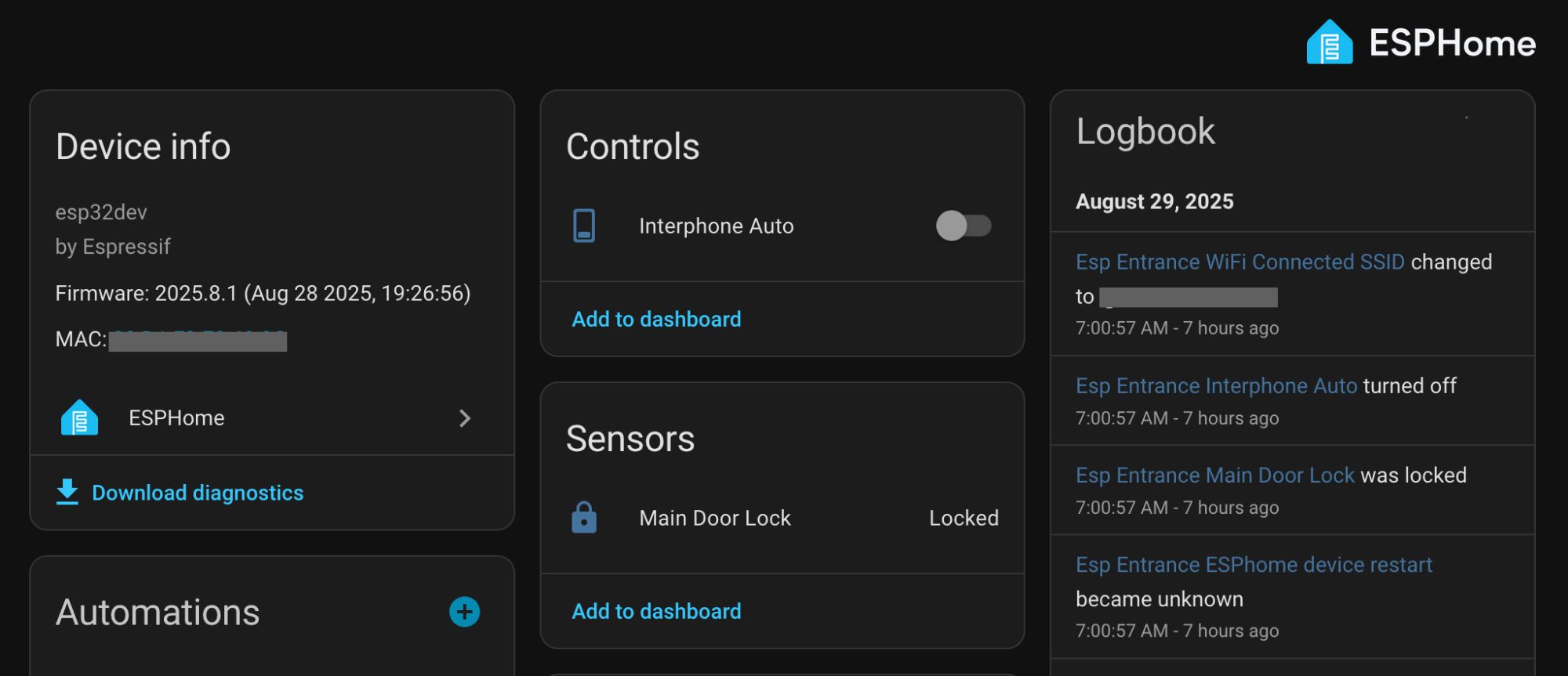
Clicks Nice! 🚀🚀🚀
Building the RF433 Gateway
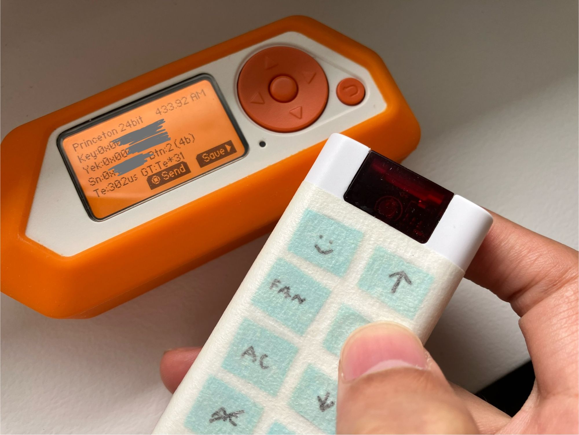
RF433 is a very basic way to communicate wirelessly. It operates by using 24-bit Princeton protocol to send a simple number to a receiver via a 433MHz radio signal. Most cheap RF433 buttons and remote controls use this protocol.
The benefit of RF433 is that it's super cheap and easy to use. I can easily decode the signal using my trusty Flipper Zero. The downside is that it's not very secure, as the signal can be easily intercepted and replayed. However, for my use case, where I just need to toggle lights and appliances, it's sufficient.
Plan for RF433 Gateway
While ESPHome supports RF433 receiver out of the box, the main problem is that it does not support aggregating the reading from multiple receivers. This is a problem because I want to use multiple RF433 receivers to cover different areas of my apartment, especially since my apartment has 2 floors.
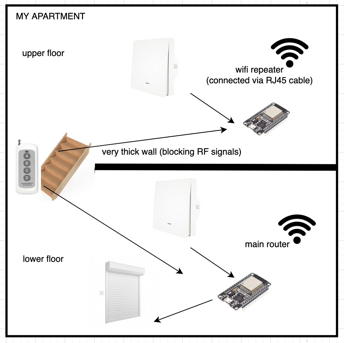
In the diagram above, I took an example of a remote controller where both of the receivers can pick up the signal. In this case, I need to void duplicate messages from both receivers.
To solve this problem, I decide to write a custom hassio add-on that will aggregate the messages from multiple ESPHome nodes and debouce them. The ESP controllers will communicate with the add-on via UDP messages for simplicity.
And lastly, I will also allow the controller to send RF433 messages, so that I can use RF433 remotes to control the rolling shutters.
First Prototype
The hardware I used for the RF433 gateway is an ESP-WROOM-32 module, which is a popular ESP32 variant with built-in WiFi and Bluetooth. I also used the RXB6 module for receiving and the FS1000A module for sending RF433 signals.
The wiring is pretty straightforward:
- VCC to 3.3V
- GND to GND
- FS1000A receiver DATA to D4
- RXB6 transmitter DATA to D17
- A simple 20cm wire is connected to the ANT pin (for transmitter, you need to solder it)
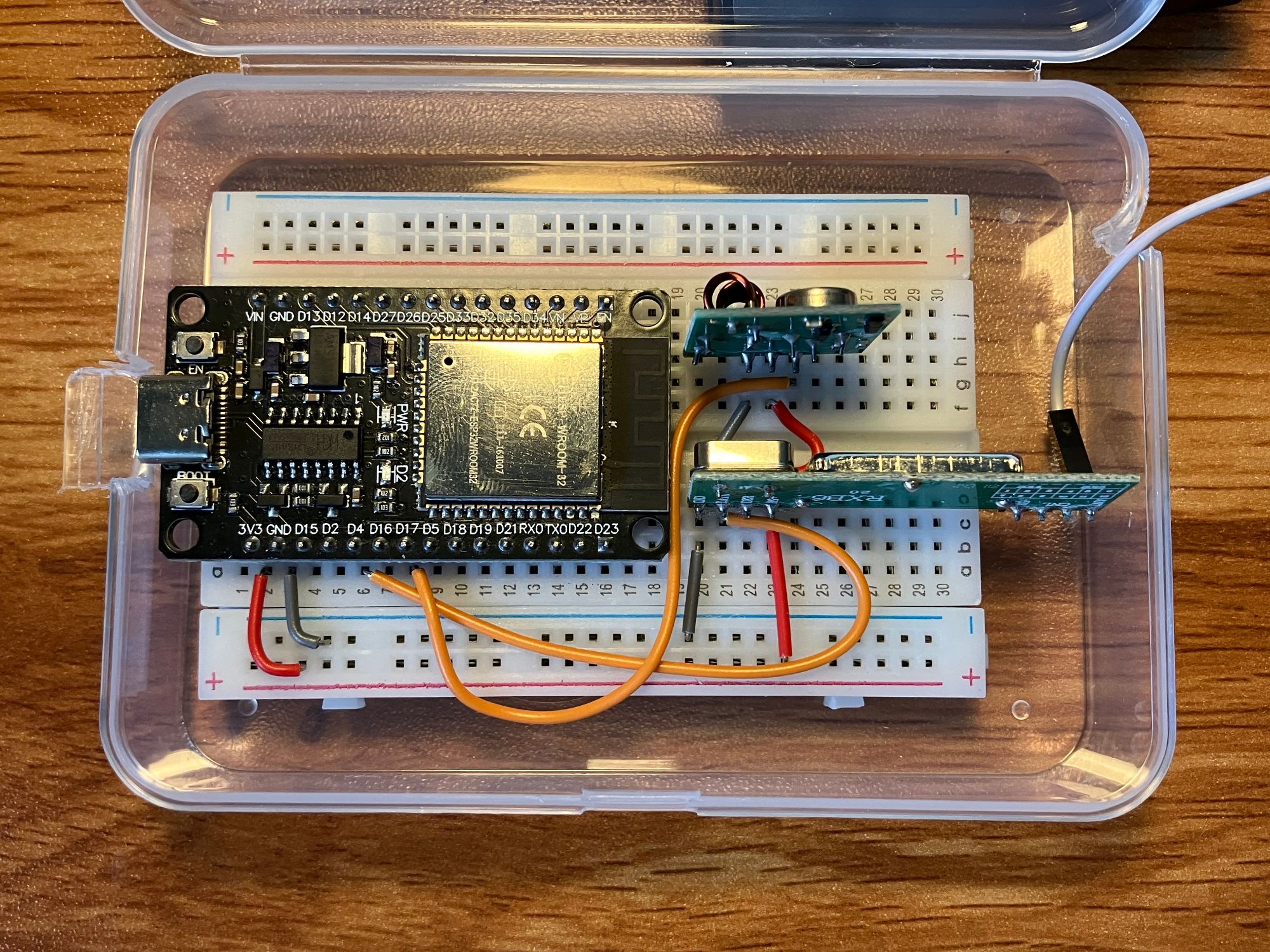
For the C++ code, I setup platformio with the following platformio.ini:
[env:espwroom32]
platform = espressif32
framework = arduino
board = upesy_wroom
monitor_speed = 115200
lib_deps =
  sui77/rc-switch@^2.6.4
Write a simple test program to test the RF433 receiver and transmitter using the examples from rc-switch library:
RCSwitch mySwitchRX = RCSwitch();
RCSwitch mySwitchTX = RCSwitch();

void setup() {
  Serial.begin(9600);
  mySwitchRX.enableReceive(4); // receiver pin D4
  mySwitchTX.enableTransmit(17); // transmitter pin D17

  // test sending
  mySwitchTX.setProtocol(1);
  mySwitchTX.setRepeatTransmit(10);
  mySwitchTX.send(123456, 24); // send code 123456 with 24 bits
  Serial.println("Sent 123456 with 24 bits");
}

void loop() {
  if (mySwitchRX.available()) {
    Serial.print("Received ");
    Serial.print( mySwitchRX.getReceivedValue() );
    Serial.print(" / ");
    Serial.print( mySwitchRX.getReceivedBitlength() );
    Serial.print("bit ");
    mySwitchRX.resetAvailable();
  }
}
Run the code, and use the Serial Monitor to check if the receiver can pick up the signal from an RF433 remote control.
Sent 123456 with 24 bits
Received 12345678 / 24bit
Pressing a button on the remote control, I can see the code being printed on the Serial Monitor. Success!
Received 55236238 / 24bit
Received 55236238 / 24bit
Received 55236230 / 24bit
Received 55236230 / 24bit
Integrate with ESPHome
Now that the basic RF433 functionality is working, I can integrate it with ESPHome. For that, we will need to dive into ESPHome's External Components feature, which allows us to include custom C++ code in the ESPHome build process.
I extend the empty_text_sensor example to create a custom RF433 receiver component. I made these changes:
- Inherit the class
PollingComponentto allow using theloop()function (the code that checks for RF433 and UDP events) - Add
RCSwitchandArduinoJsonas header-only libraries. This is because I couldn't find a way to reuse platformio'slib_depsin ESPHome.
Unfortunately, my code is pretty messy, so I won't share it publicly. But basically, it's built using these examples:
- The code above for sending and receiving RF433 using
RCSwitch - Sending and receiving UDP packets. NOTE:
Udp.begin()must be called insideloop()instead ofsetup(), this is because the network stack is not yet ready in ESPHome'ssetup().
The overall logic is:
- When an RF433 code is received, a JSON message is broadcasted via UDP
- When a UDP message is received, it is parsed and the RF433 code is sent via the transmitter
Custom add-on
The custom add-on is a simple NodeJS script that listens for UDP messages from the ESPHome nodes, debounces them, and sends webhooks to hassio. It looks like this:
const dgram = require('dgram');

const PORT_SERVER_UDP = 41234; // Port to listen for UDP messages
const DEBOUNCE_TIME_MS = 500; // Debounce time in milliseconds

const receivedCodes = new Map(); // Map to store received codes and their timestamps

const udpServer = dgram.createSocket('udp4');

udpServer.on('message', (msg, rinfo) => {
  console.log(`UDP server got: ${msg}`);
  try {
    const data = JSON.parse(msg.toString());
    if (data.event === 'rf433_recv' && data.code) {
      const now = Date.now();
      const lastReceived = receivedCodes.get(data.code) || 0;
      if (now - lastReceived > DEBOUNCE_TIME_MS) {
        receivedCodes.set(data.code, now);

        // Send webhook to hassio
        console.log(`Sending webhook for code: ${data.code}`);
        fetch('http://127.0.0.1:8123/api/webhook/rf433_code_' + data.code, {
          method: 'POST',
        });
      } else {
        // silently ignore duplicate within debounce time
      }
    }
  } catch (error) {
    console.error('UDP server Error parsing message:', error, '\nMessage:', msg.toString());
  }
});

udpServer.bind(PORT_SERVER_UDP);
I tested it on my laptop first by running the script, and press the buttons on the RF433 remote. I can see the UDP messages being received and webhooks being sent.
UDP server got: {"event":"rf433_recv","code":55236238,"bits":24}
Sending webhook for code: 55236238
Then, I packaged it as a hassio add-on template using the following Dockerfile:
FROM node:22.11.0-bookworm-slim

ENV DEBIAN_FRONTEND=noninteractive

WORKDIR /app

COPY app/package.json .
COPY app/package-lock.json .
RUN npm ci

COPY app .

CMD ["npm", "start"]
And this is the config.yaml for the add-on:
---
name: # you name it
version: dev
slug: # you name it
description: # you name it
panel_icon: mdi:home-circle
startup: services
init: false
arch:
  - aarch64
  - amd64
  - armv7
host_network: true # IMPORTANT: use host network to receive UDP packets
stdin: true
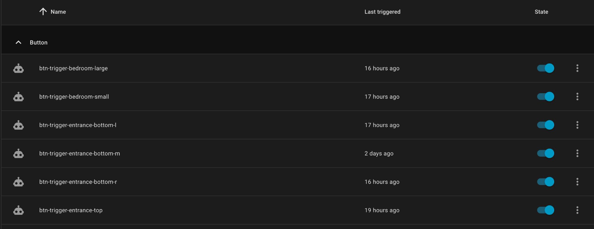
Once the add-on is installed and started, I can add a webhook automation in hassio to handle each of the buttons:
Sending RF433 codes from hassio
For the reversed direction, sending RF433 codes from hassio, I can use the stdio input of the add-on. This is a bit hacky, but it works. The add-on will listen for lines of text from stdin, and when it receives a line that starts with send_rf433, it will parse the code and send it via UDP to the ESPHome node.
import readline from 'node:readline';

const rl = readline.createInterface({
  input: process.stdin,
  output: process.stdout,
  terminal: false
});

rl.on('line', (line: string) => {
  const inputStr = line.trim();
  if (inputStr) {
    console.log('Received from stdin:', inputStr);
    try {
      const data = JSON.parse(inputStr);
      // example: {"event": "rf433_send", "code": 64236750, "bits": 24}
      if (data['event'] === 'rf433_send') {
        sendUdp(data); // you need to write this function yourself
      } else {
        console.warn('Unknown event type:', data['event']);
      }
    } catch (error) {
      console.error('Error parsing JSON:', error);
    }
  }
});

rl.once('close', () => {
  console.log('stdin stream closed');
});
Then, from hassio, I can make a script to send a command to the add-on via stdin:
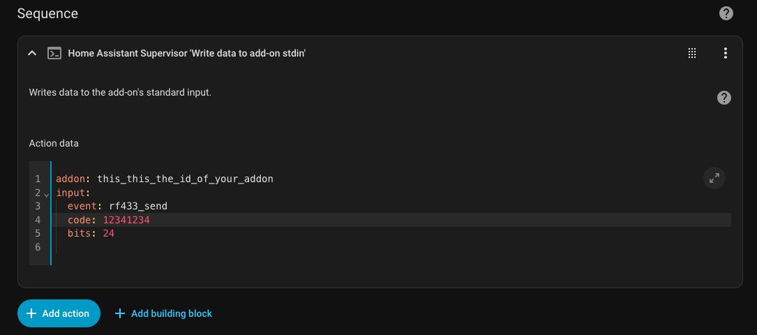
Testing with the code from my rolling shutter remote, and it works!
Conclusion
In this part, I covered the implementation of the RF433 gateway using ESPHome and a custom hassio add-on. The ESPHome nodes are responsible for receiving and sending RF433 codes, while the add-on aggregates the messages and debounces them before sending webhooks to hassio.
In the next part, I will cover the integration of other smart devices, such as sensors, HVAC and more. Stay tuned!
